Thursday, July 16, 2015

VLAN Routing

In this article we will discuss about the configuration on the switches of the TSHOOT Demo ticket. We post the topology here for your reference.
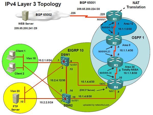
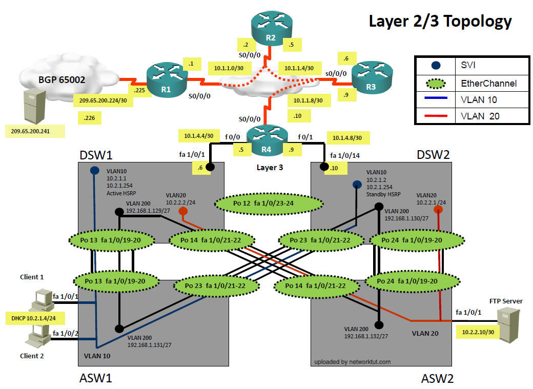
Layer2/3 topology
Layer2_topology.jpg
Main Configuration on DSW1 and ASW1
DSW1:
ip routing
vtp mode transparent
!
vlan 10
name CLIENT_VLAN
!
vlan 98
name NATIVE_VLAN
!
vlan 99
name PARKING_LOT
!
interface range Fa1/0/2 – 18, Fa1/0/20 – 48, Gi1/0/1 – 4
switchport access vlan 99
switchport mode access
shutdown
!
interface FastEthernet1/0/1
description Link to R4
no switchport
ip address 172.16.1.14 255.255.255.252
!
interface FastEthernet1/0/19
description Trunk to ASW1
switchport access vlan 99
switchport trunk encapsulation dot1q
switchport trunk native vlan 98
switchport trunk allowed vlan 10,98
switchport mode trunk
!
interface Vlan10
ip address 172.16.2.1 255.255.255.0
!
router eigrp 16
network 172.16.1.0 0.0.0.255
network 172.16.2.0 0.0.0.255
passive-interface default
no passive-interface FastEthernet0/1
ASW1:
vtp mode transparent
!
vlan 10
name CLIENT_VLAN
!
vlan 98
name NATIVE_VLAN
!
vlan 99
name PARKING_LOT
!
interface FastEthernet1/0/1
switchport access vlan 10
switchport mode access
spanning-tree portfast
!
interface FastEthernet1/0/2
switchport access vlan 10
switchport mode access
spanning-tree portfast
!
interface range Fa1/0/3 – 18, Fa1/0/20 – 48, Gi1/0/1 – 4
switchport access vlan 99
switchport mode access
shutdown
!
interface FastEthernet1/0/19
description Link to DSW1
switchport trunk encapsulation dot1q
switchport trunk native vlan 98
switchport trunk allowed vlan 10,98
switchport mode trunk
From the output above we learn that:
+ VTP is disabled on both switches.
+ DSW1: running EIGRP (Layer 3 switch) while ASW1 is pure layer 2 switch
+ Configuration VLANs on both switches as follows:
a) VLAN 10: CLIENT_VLAN (two computers are assigned to this VLAN)
b) VLAN 98: NATIVE_VLAN (no ports are assigned to this VLAN. This VLAN exists just to make sure traffic from other VLANs are tagged)
c) VLAN 99: PARKING_LOT (unused ports are assigned to this VLAN)
+ Fa1/0/19 is the trunking port between two switches
+ Only VLAN 10 and 98 are allowed to go through 2 switches.
+ Default gateway on two PCs are 172.16.2.1 which is the IP address of Interface VLAN 10 on DSW1.
+ EIGRP updated is only sent and received on fa1/0/1 which connects from DSW1 to R4
+ On ASW1, spanning-tree PortFast feature is enabled on fa1/0/1 & fa1/0/2 which are connected to two PCs.
Note: On DSW1, under interface Fa1/0/19 we can see this command:
switchport access vlan 99
but this port is set as trunk port (switchport mode trunk) so how can a command for access port be there? Well, in fact we have set this port to trunk mode so the switchport access vlan 99 command has no effect at all. It only affects when you change this port to an access port and this port would be assigned to VLAN 99.
The IP address of interface VLAN 10 (172.16.2.1/24) is set as the default gateway on Host 1 & Host 2. In general, a Switch Virtual Interface (SVI) represents a logical Layer 3 interface on a switch and it can be used to interconnect Layer 3 networks using routing protocols (like RIP, OSPF, EIGRP…). When packets reach this SVI, the Layer 3 switch will look up in its routing table to see if there is an entry to route the packets to the destination. In this case, packets sent from Host 1 & 2 reach 172.16.2.1 (because this IP is also the default gateway set on Host 1 & 2), then DSW1 looks up in its routing table for a suitable entry to the destination.
Quick reminder: VLAN interfaces or switched virtual interfaces (SVI) are logical layer 3 routable interface. Generally, SVIs are often used to accomplish InterVLAN routing on a Layer 3 switch. From there, you would point the client devices to the VLAN interface to use as it’s default gateway. When a packet arrives on that interface, the Layer 3 switch will do a routing table lookup and perform routing process like a normal packet.
In the next part we will try to do above topology in Packet Tracer. But Packet Tracer does not understand redistribute static route into EIGRP so we simplify the configuration by running EIGRP on all routers.
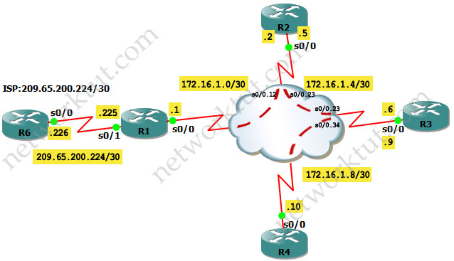
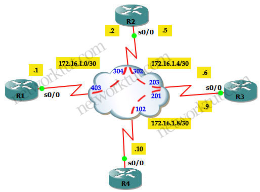
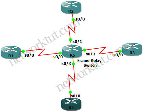
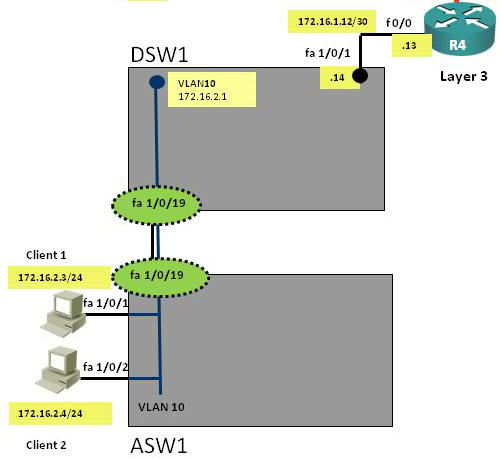
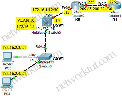
Physical topology
VLAN_topology.jpg
Tasks in the lab:
+ VTP is disabled on both switches.
+ DSW1: running EIGRP (Layer 3 switch) while ASW1 is pure layer 2 switch
+ Configuration VLANs on both switches as follows:
a) VLAN 10: CLIENT_VLAN (two computers are assigned to this VLAN)
b) VLAN 98: NATIVE_VLAN (no ports are assigned to this VLAN. This VLAN exists just to make sure traffic from other VLANs are tagged)
c) VLAN 99: PARKING_LOT (unused ports are assigned to this VLAN)
+ Fa0/19 is the trunking port between two switches
+ Only VLAN 10 and 98 are allowed to go through 2 switches.
+ Default gateway on two PCs are 172.16.2.1 which is the IP address of Interface VLAN 10 on DSW1.
+ EIGRP updated is only sent and received on fa0/1 which connects from DSW1 to R4
+ On ASW1, spanning-tree PortFast feature is enabled on fa0/1 & fa0/2 which are connected to two PCs.
Configuration
ASW1
hostname ASW1
!
vtp mode transparent
!
vlan 10
name CLIENT_VLAN
!
vlan 98
name NATIVE_VLAN
!
vlan 99
name PARKING_LOT
!
interface FastEthernet0/1
switchport access vlan 10
switchport mode access
spanning-tree portfast
!
interface FastEthernet0/2
switchport access vlan 10
switchport mode access
spanning-tree portfast
!
interface FastEthernet0/19
description Link to DSW1
switchport trunk encapsulation dot1q
switchport trunk native vlan 98
switchport trunk allowed vlan 10,98
switchport mode trunk
DSW1
hostname DSW1
ip routing
!
vtp mode transparent
!
vlan 10
name CLIENT_VLAN
!
vlan 98
name NATIVE_VLAN
!
vlan 99
name PARKING_LOT
!
interface FastEthernet0/1
description Link to R4
no switchport
ip address 172.16.1.14 255.255.255.252
no shutdown
!
interface FastEthernet0/19
description Trunk to ASW1
switchport access vlan 99
switchport trunk encapsulation dot1q
switchport trunk native vlan 98
switchport trunk allowed vlan 10,98
switchport mode trunk
!
interface Vlan10
ip address 172.16.2.1 255.255.255.0
!
router eigrp 16
network 172.16.1.0 0.0.0.255
network 172.16.2.0 0.0.0.255
passive-interface default
no passive-interface FastEthernet0/1
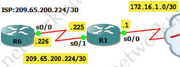
R0
hostname R0
!
interface FastEthernet0/0
ip address 172.16.1.13 255.255.255.252
no shutdown
!
interface FastEthernet0/1
ip address 209.65.200.225 255.255.255.252
no shutdown
!
router eigrp 16
network 172.16.0.0
network 209.65.200.0
R1
hostname R1
!
interface FastEthernet0/0
ip address 209.65.200.226 255.255.255.252
no shutdown
!
router eigrp 16
network 209.65.200.0
Also configure IP addresses and default gateways of the two computers as follows:
PC0
IP: 172.16.2.3/24
Default gateway: 172.16.2.1
PC1
IP: 172.16.2.4/24
Default gateway: 172.16.2.1
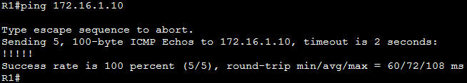
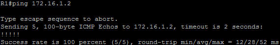
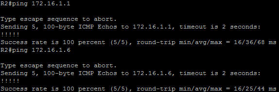
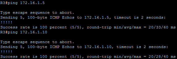
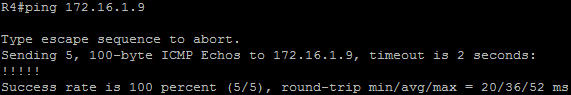
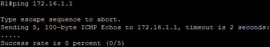
Now two hosts can ping 209.65.200.226.

EIGRP over Frame Relay and EIGRP Redistribute Lab

In the previous Frame Relay Point-to-Point Subinterface lab we have set up Layer 2 connection via Frame Relay but only adjacent routers can ping each other. For example R1 can ping R2 and R2 and ping R3 but R1 cannot ping R3. This is because R2 connects with R1 and R3 via point-to-point interfaces and they use separate subnets. In this lab we will use EIGRP to advertise these routes so that “remote” routers can ping each other.
topology.jpg
IOS used in this lab: c3640-jk9s-mz.124-16.bin
Tasks for this lab:
+ Configure EIGRP so that R1, R2, R3 and R4 can see and ping each other
+ Configure default route on R1 to 209.65.200.226 of R6
+ Advertise that default route to other routers via EIGRP so that every router can go to the Internet
Configure EIGRP on R1, R2, R3 and R4
R1
router eigrp 16
network 172.16.0.0
R2
router eigrp 16
network 172.16.1.0 0.0.0.255
R3
router eigrp 16
network 172.16.1.4 0.0.0.3
network 172.16.1.9 0.0.0.0
R4
router eigrp 16
network 172.16.1.0 0.0.0.25
The configuration of EIGRP is simple but please keep in mind that the “network” command really doesn’t advertise the network in that command. It enables EIGRP on the interface matched by the “network” command. For example, on R2 the “network 172.16.1.0 0.0.0.255″ command instructs R2 to search all of its active interfaces (including subinterfaces) and R2 finds out the IP addresses of s0/0.12 and s0/0.23 subinterfaces belong to “172.16.10 0.0.0.255″ network so R2 enables EIGRP on these subinterfaces. Another example is on R3, the “network 172.16.1.4 0.0.03″ will enable EIGRP on s0/0.23 subinterface only. Without the “network 172.16.1.9 0.0.0.0″ command, EIGRP would not be enabled on s0/0.34 subinterface. You can verify which interfaces are running EIGRP by the show ip eigrp interfaces command.
So any mask you put in your network command, as long as it matches or includes the IP address on a particular interface than you are good to go. And if you are lazy, just put the “network 0.0.0.0 255.255.255.255″ command on each router, this will tell that router “enable EIGRP on all of my active interfaces (regardless what their IP addresses), please” because the wildcard 255.255.255.255 indicates that the router does not care about what network is using.
Note: The “network” command also works in the same way for OSPF, RIP and other Interior Gateway Protocol (IGP) routing protocols, except for BGP (which is an EGP routing protocol). In BGP, the function of a network statement is to tell the router to search the IP routing table for a particular network, and if that network is found, originate it into the BGP database.
After typing the configuration above we can ping remote routers now. For example the ping from R1 to R4 will be successful.
R1_ping172.16.1.10.jpg
And the routing table of R1 contains all networks in this topology:
R1_show_ip_route.jpg
Other routers’ routing tables are the same so I will not post them here.
Redistribute static route into EIGRP
In this part we will learn how default route to Internet (or to ISP router) should be advertised. Suppose R6 in the topology is the ISP router.
ISP_topology.jpg
R1
interface s0/1
ip address 209.65.200.225 255.255.255.252
no shutdown
R6
interface s0/0
ip address 209.65.200.226 255.255.255.252
no shutdown
!
interface Loopback0
ip address 209.65.200.241 255.255.255.252


You can’t run an IGP routing protocol (like OSPF, EIGRP) on the ISP router so the most simple way to send traffic to the ISP router is to use static route. So on R1 we will set up a static route to R6, we can do it via 3 ways:
R1(config)#ip route 0.0.0.0 0.0.0.0 s0/1
or
R1(config)#ip route 0.0.0.0 0.0.0.0 209.65.200.226
or
R1(config)#ip route 0.0.0.0 0.0.0.0 s0/1 209.65.200.226
Note: Just for your information about static route, the paragraph below is quoted fromhttp://www.cisco.com/en/US/docs/security/asa/asa82/configuration/guide/route_static.html.
“Static routes remain in the routing table even if the specified gateway becomes unavailable. If the specified gateway becomes unavailable, you need to remove the static route from the routing table manually. However, static routes are removed from the routing table if the specified interface goes down, and are reinstated when the interface comes back up”.
I want to notice that in all three cases of the ip route statements above, the static route will be removed in the routing table when s0/1 of R1 or s0/0 of R6 goes down. In other word, if you point a static route to a broadcast interface, the route is inserted into the routing table only when the broadcast interface is up.
As you see the third case use both the local outgoing interface and the next-hop IP address. In fact in the topology above it has no more effect than the second case (only use next-hop IP address). The third case is only better in the case the remote interface goes down and next-hop IP can be reachable through a recursive route (but I haven’t test it).
For more information about “ip route” command, please read the following link:http://www.cisco.com/en/US/tech/tk365/technologies_tech_note09186a00800ef7b2.shtml
Ok, now R1 knows where to throw the packets when it can’t find a suitable destination for them. The routing table of R1 now shows the default route to 209.65.200.226. Notice that by default, static routes have an Administrative Distance of 1.
R1_show_ip_route_added_static_route.jpg
But R2, R3 and R4 still do not know! We can configure a static route on each of them but it is not a good thing to do. A better way to advertise this static route to R2, R3 and R4 is via the configured EIGRP. How can we do that? Ahh, we will redistribute this static route into EIGRP and EIGRP will advertise it for us. On R1:
router eigrp 16
redistribute static metric 64 100 100 100 1500
Note: The ip route command is not automatically carried in routing updates like the ip default-network command (in some routing protocols). You must redistribute the static command into a routing protocol for it to be carried.
The 5 parameters are used for redistribution into EIGRP are Bandwidth, Delay, Reliability, Load, MTU. For example the redistribution above is corresponding to Bandwidth = 64Kbit, Delay = 1000ms, Reliability=100, Load=100, MTU=1500 bytes. Notice that the unit of Delay used in the redistribution into EIGRP is tens of microsecond so we must divide Delay (in millisecond) by 10.
Now the routing tables of other routers (than R1) also learn this default route as an EIGRP external route (marked with D*EX). For example the routing table of R2:
R2_show_ip_route_after_redistribute.jpg
The default administrative distance for EIGRP externals (routes redistributed into EIGRP) is 170.
By default, K1 = 1, K2 = 0, K3 = 1, K4 = 0, K5 = 0 so the metric formula for EIGRP is:
metric = (107 / Slowest Bandwidth of all interfaces[Kbit] + Sum of delay[ten-of-millisecond] ) * 256
You can check the total delay and minimum bandwidth used to calculate EIGRP metric via the “show ip route <route>” command:
R2_show_ip_route_0.0.0.0.jpg
Therefore the EIGRP metric here should be:
metric = (107 / 64 + 2100) * 256 = 40537600
Note: We are not sure why the unit of delay here is microsecond. But if we consider “microsecond” millisecond we will get the correct metric, otherwise we never get the correct result. And the unit of sum of delay used to calculate EIGRP metric is ten-of-millisecond so we have to divide the total delay by 10 (21000 / 10 = 2100).
We can verify R4 has learned the default route, too:
R4_show_ip_route_after_redistribute.jpg
R4 also knows it has to route unknown traffic to 172.16.1.9. Also notice 172.16.1.9 now becomes the “gateway of last resort” of R4.
The GNS3 initial and final configs can be downloaded here:

Frame Relay Point-to-Point SubInterface GNS3 Lab

In this lab we will try to run a Frame Relay topology same as the one posted in TSHOOT demo ticket. The logical and physical topologies of this lab are shown below:
Logical topology:
Topology_logical.jpg
Tasks in this lab:
+ Configure static mappings on R1 and R4.
+ Configure point-to-point subinterface on R2 & R3.
+ All routers must be able to ping themselves.
Physical topology:
Topology.jpg
IOS used in this lab: c3640-jk9s-mz.124-16.bin
We will use a router (R5) to simulate the Frame Relay switch instead of using a Frame Relay Switch in GNS3. First we will configure the Frame Relay switch with the DLCIs shown above. In fact the DLCIs in the topology are not very logical, especially DLCIs 304 & 403 for the links between R1 & R2, but well… let’s configure them.
Note: If you are not sure about Frame Relay theory, please read Frame Relay tutorial first.
Configuration
Configure Frame Relay Switch:
We should change the name of R5 to FRSW (Frame Relay Switch).
R5(config)#hostname FRSW
The very first command to turn on the frame relay switching feature on FRSW:
FRSW(config)#frame-relay switching
FRSW(config)#int s0/0
FRSW(config-if)#encapsulation frame-relay
FRSW(config-if)#frame-relay intf-type dce
FRSW(config-if)#clock rate 64000
FRSW(config-if)#frame-relay route 403 interface serial 0/1 304
FRSW(config-if)#no shutdown
FRSW(config)#int s0/1
FRSW(config-if)#encapsulation frame-relay
FRSW(config-if)#frame-relay intf-type dce
FRSW(config-if)#clock rate 64000
FRSW(config-if)#frame-relay route 304 interface serial 0/0 403
FRSW(config-if)#frame-relay route 302 interface serial 0/2 203
FRSW(config-if)#no shutdown
FRSW(config)#int s0/2
FRSW(config-if)#encapsulation frame-relay
FRSW(config-if)#frame-relay intf-type dce
FRSW(config-if)#clock rate 64000
FRSW(config-if)#frame-relay route 203 interface serial 0/1 302
FRSW(config-if)#frame-relay route 201 interface serial 0/3 102
FRSW(config-if)#no shutdown
FRSW(config)#int s0/3
FRSW(config-if)#encapsulation frame-relay
FRSW(config-if)#frame-relay intf-type dce
FRSW(config-if)#clock rate 64000
FRSW(config-if)#frame-relay route 102 interface serial 0/2 201
FRSW(config-if)#no shutdown
+ The frame-relay intf-type dce command specifies the interface to handle LMI like a Frame Relay DCE device. This command also enables FRSW to function as a switch connected to a router. And the clock rate is necessary on the DCE end of the connection so we have to put it here (but in fact not all IOS versions require this, you can check or verify the DCE and clock rate with the show controller serial x/y command).
+ The frame-relay route 403 interface serial 0/1 304 command means frame-relay traffic comes to FRSW which has a DLCI of 403 will be sent to interface Serial0/1 with a DLCI of 304.
Also please notice that there is no IP address configured on the Frame Relay Switch.
We can verify the configuration of the FRSW with show frame-relay route command:
FRSW_show_frame_route.jpg
Note: The output above is taken after all routers have been configured so if you do this command in your lab at this moment the Status would be Inactivebecause you have not turned on the Serial interfaces on R1, R2, R3, R4.
Configure R1, R2, R3 and R4:
First I show all the configuration but you should type them manually to see how it works instead of pasting all of them at the same time.
R1:
interface s0/0
ip address 172.16.1.1 255.255.255.252
encapsulation frame-relay
no frame-relay inverse-arp
frame-relay map ip 172.16.1.1 403 broadcast
frame-relay map ip 172.16.1.2 403
no shutdown
(good to explain first broadcast: https://learningnetwork.cisco.com/thread/35698)
R2:
interface Serial0/0
no ip address
encapsulation frame-relay
no shutdown
!
interface Serial0/0.12 point-to-point
description Link to R1
ip address 172.16.1.2 255.255.255.252
frame-relay interface-dlci 304
!
interface Serial0/0.23 point-to-point
description Link to R3
ip address 172.16.1.5 255.255.255.252
frame-relay interface-dlci 302
R3:
interface Serial0/0
no ip address
encapsulation frame-relay
no frame-relay inverse-arp
no shutdown
!
interface Serial0/0.23 point-to-point
description Link to R2
ip address 172.16.1.6 255.255.255.252
frame-relay interface-dlci 203
!
interface Serial0/0.34 point-to-point
description Link to R4
ip address 172.16.1.9 255.255.255.252
frame-relay interface-dlci 201
R4:
interface Serial0/0
description Link to R3
ip address 172.16.1.10 255.255.255.252
encapsulation frame-relay
frame-relay map ip 172.16.1.9 102 broadcast
frame-relay map ip 172.16.1.10 102
no frame-relay inverse-arp
no shutdown
There are somethings I wish to explain. For example on R1 under interface s0/0 we see the command:
frame-relay map ip 172.16.1.1 403 broadcast
The frame-relay map command performs static addressing mapping and it disables Inverse ARP on the specified DLCI. This command is supported on the physical interface and it should be used when the far end Frame Relay device does not support Inverse ARP. If we choose to disable Inverse ARP, we must perform a static mapping of L2 to L3, as well as associate the DLCI to the interface.
The IP address 172.16.1.1 is the IP address of R1 itself so why do we need this command? The answer is: without this command, you cannot ping from R1 to itself (ping to it own IP address may be a lab requirement, a fun test…) because that IP address does not exist in the Frame Relay map table and Frame Relay does not know which DLCI it should use to send the frames to this destination. You can check this with the “debug frame-relay packet” command to see the error Serial0/0:Encaps failed–no map entry link 7(IP). By adding a static map to the DLCI used for a neighbor, when we ping to itself, the router will send ICMP to that neighbor and the neighbor will reply back to R1.
Now let’s discuss about the broadcast keyword in the above command. First, please notice that the “broadcast” keyword here is used for both multicast and broadcast traffic. By default, Frame Relay is a non-broadcast multiple access (NBMA) network and does not support broadcast or multicast traffic. So without the broadcast keyword, dynamic routing protocols such as EIGRP, OSPF and RIPv2 would not be able to advertise multicast route updates over the corresponding DLCI. Therefore we should always add this keyword in the “frame-relay map” command. But remember this: we only use one broadcastkeyword for each DLCI regardless how many IP addresses are used along with. So the commands below:
frame-relay map ip 172.16.1.1 403 broadcast
frame-relay map ip 172.16.1.2 403
are same as:
frame-relay map ip 172.16.1.1 403
frame-relay map ip 172.16.1.2 403 broadcast
You should never use more then one broadcast keyword for one DLCI like this:
frame-relay map ip 172.16.1.1 403 broadcast
frame-relay map ip 172.16.1.2 403 broadcast
or you will end up with multiple copies of the packets being transported and received.
Configuring static map statements (like frame-relay map ip command) automatically disables Inverse ARP so in the configuration of R1, the no frame-relay inverse-arp command is in fact not necessary.
Note: Physical interfaces have Inverse ARP enabled by default
That is all explanation for R1. Next we will discuss about the configuration of R2 and R3 (they are very identical). Under subinterface (like Serial0/0.12 point-to-point on R2) we see the command:
frame-relay interface-dlci 304
We notice that in this command only the DLCI is specified and this command just associates the DLCI with the subinterface. This is because point-to-point network only connects with one remote destination. Therefore this command is mostly used under point-to-point subinterface (but it can be still used on physical interface although it has no effect because all unassigned DLCIs belong to that physical interface by default). On point-to-point subinterface, Inverse ARP requests are not sent out regardless if it is enabled on the physical interface or not. It is also not required to enable or disable Inverse ARP, because there is only a single remote destination on a PVC and discovery is not necessary. Also notice that the frame-relay map command is not allowed on a point-to-point subinterface.
Note: Using subinterface can avoid the split-horizon problem.
We can check which type of mapping was configured with the command “show frame-relay map”:
Dynamic means the mapping was done using Inverse ARP.
Static means the mapping was done manually.
For example on R1 static mapping is being used:
R1_show_frame-relay_map.jpg
Let’s check R2:
R2_show_frame-relay_map.jpg
Hmm, on R2 we don’t see the word “static” or “dynamic”. There are some confusions about the “frame-relay interface-dlci” command if it belongs to dynamic mapping or static mapping. But there is an opinion saying that point-to-point does not use the principle of static or dynamic mapping so it is not listed here. Well, the decision is yours.
Also you can notice that no Layer 3 addresses are shown in above command.
On the “show frame-relay map” outputs above you can see the Frame Relay’s statuses are all active. There are 4 PVC statuses:
Active: Both sides of the PVC are up and communicating.
Inactive: Local router received status about the DLCI from the frame-switch, the other side is down.
Deleted: Indicates a local config problem. The frame-switch has no such mapping and responded with a “deleted message”.
Static: Indicates that LMI was turned off with the “no keepalives”.
The outputs of the show frame-relay map command on R3 & R4 are very identical to R1 & R2, I also post here just for your reference:
R3_show_frame-relay_map.jpg
R4_show_frame-relay_map.jpg
That’s all I wish to explain, let’s check if the pings work…
R1_ping_172.16.1.2.jpg
R2_ping_172.16.1.1_172.16.1.6.jpg
R3_ping 172.16.1.5_172.16.1.10.jpg
R4_ping_172.16.1.9.jpg
So all the pings to the neighbors are working. On R1 you can try pinging itself and it will successful too. If you disable the frame-relay map ip 172.16.1.1 403 broadcast command (use no frame-relay map ip 172.16.1.1 403 broadcast), R1 cannot ping itself anymore:
R1_ping_172.16.1.1_itself.jpg
In this Frame Relay lab we only set path for adjacent routers. We can’t ping between R1 to R3 for example. There are two solutions so that R1 can ping R3:
+ Use multipoint subinterfaces on R2 (disable Inverse ARP and set two static frame-relay mappings on both R1 and R3)
+ Enable a routing protocol (static routing, EIGRP, OSPF, RIP…)
The GNS3 initial and final configs can be downloaded here:
————————————————————————————————————————————-

HSRP IP Route Tracking

In this article we will discuss about HSRP and do a lab on it.
Quick reminder about HSRP
+ Hot Standby Router Protocol (HSRP) is a Cisco proprietary protocol.
+ With HSRP, two or more devices support a virtual router with a fictitious MAC address and unique IP address
+ Hosts use this IP address as their default gateway and the MAC address for the Layer 2 header
+ The virtual router’s MAC address is 0000.0c07.ACxx , in which xx is the HSRP group. Multiple groups (virtual routers) are allowed.
+ The Active router forwards traffic. The Standby router is backup and monitors periodic hellos (multicast to 224.0.0.2,
UDP port 1985) to detect a failure of the active router.
+ The active router is chosen because it has the highest HSRP priority (default priority is 100). In case of a tie, the router
with the highest configured IP address wins the election
+ A new router with a higher priority does not cause an election unless it is configured to preempt.
HSRP States
+ Initial: HSRP is not running.
+ Learn: The router does not know the virtual IP address and is waiting to hear from the active router.
+ Listen: The router knows the IP and MAC of the virtual router, but it is not the active or standby router.
+ Speak: Router sends periodic HSRP hellos and participates in the election of the active router.
+ Standby: Router monitors hellos from active router and assumes responsibility if active router fails.
+ Active:Router forwards packets on behalf of the virtual router.
Load balancing traffic across two uplinks to two HSRP routers with a single HSRP group is not possible. The trick is to use two
HSRP groups:
+ One group assigns an active router to one switch.
+ The other group assigns another active router to the other switch.
(Reference: SWITCH official Certification Guide)
That is all for the boring HSRP theory, let do a lab to understand more about HSRP! We will use the topology below for this lab:
HSRP_Tracking_Topology.jpg
IOS used: c3640-jk9s-mz.124-16.bin
Tasks in this lab:
+ Configure IP addresses as shown and run EIGRP on R2, R3, R4
+ Configure HSRP: R2 is the Active HSRP while R3 is the Standby HSRP
+ Tracking route to 4.4.4.4, traffic should goes to R3 once the route to 4.4.4.4 is lost in R2 or the metric to R4’s loopback interface increases.
IP Address and EIGRP Configuration
R1 (configured as a host)
no ip routing
ip default-gateway 123.123.123.254 //This is the virtual IP of HSRP group
interface FastEthernet0/0
ip address 123.123.123.1 255.255.255.0
no shutdown
R2
interface FastEthernet0/0
ip address 123.123.123.2 255.255.255.0
no shutdown
!
interface FastEthernet1/0
ip address 24.24.24.2 255.255.255.0
no shutdown
!
router eigrp 1
network 24.0.0.0
network 123.0.0.0
R3
interface FastEthernet0/0
ip address 123.123.123.3 255.255.255.0
no shutdown
!
interface FastEthernet1/0
ip address 34.34.34.3 255.255.255.0
no shutdown
!
router eigrp 1
network 34.0.0.0
network 123.0.0.0
R4
interface Loopback0
ip address 4.4.4.4 255.255.255.0
!
interface FastEthernet0/0
ip address 24.24.24.4 255.255.255.0
no shutdown
!
interface FastEthernet1/0
ip address 34.34.34.4 255.255.255.0
no shutdown
!
router eigrp 1
network 4.0.0.0
network 24.0.0.0
network 34.0.0.0
HSRP Configuration
R2
interface FastEthernet0/0
standby 10 ip 123.123.123.254
standby 10 priority 200
standby 10 preempt
R3
interface FastEthernet0/0
standby 10 ip 123.123.123.254
standby 10 priority 150
standby 10 preempt
Note: The virtual IP address of HSRP group must be in the same subnet of the IP address on this interface (Fa0/0)
After entering above commands we will see R2 takes Active state after going from Speak to Standby:
%HSRP-5-STATECHANGE: FastEthernet0/0 Grp 10 state Speak -> Standby
*Mar 1 00:10:22.487: %HSRP-5-STATECHANGE: FastEthernet0/0 Grp 10 state Standby -> Active
*Mar 1 00:10:22.871: %SYS-5-CONFIG_I: Configured from console by console
The “show standby” command on R2 confirms its state:
HSRP_Tracking_R2_show_standby.jpg
Now R2 is in HSRP Active state with virtual MAC address of 00000c07.ac0a. Notice that the last two numbers of the MAC address (0a) is the HSRP group number in hexadecimal form (0a in hexa = 10 in decimal)
The “show standby” command on R3 reveals it is in Standby state:
HSRP_Tracking_R3_show_standby.jpg
Now we will see what happens if we turn off interface Fa0/0 on R2:
R2(config)#interface fa0/0
R2(config-if)#shutdown
HSRP_Tracking_R2_show_standby_interface_down.jpg
HSRP_Tracking_R3_show_standby_interface_R2_down.jpg
As we can see, the HSRP state of R2 went back to Init while the HSRP state of R3 moved to Active.
HSRP Tracking IP Route
In this part instead of tracking an interface going up or down we can track if the metric of a route to a destination changes or not. In particular we will try to track the route to the loopback interface of R4 (4.4.4.4). First we should check the routing table of R2:
HSRP_Tracking_R2_show_ip_route.jpg
We learn that the metric to the loopback interface of R4 (4.4.4.4) is 156160 and is summarized to 4.0.0.0/8 prefix because EIGRP summarizes route by default.
Now add tracking ip routing to R2
R2(config)#track 1 ip route 4.0.0.0 255.0.0.0 metric threshold
R2(config-track)#threshold metric up 61 down 62
and on interface fa0/0 add these commands to apply the track:
R2(config)#interface fa0/0
R2(config-if)#standby 10 track 1 decrement 60
The command track ip route metric threshold is used to track the metric change of a route. For example in this case the second command threshold metric up 61 down 62 specifies the low and high thresholds.
up: Specifies the up threshold. The state is up if the scaled metric for that route is less than or equal to the up threshold. The default up threshold is 254.
down: Specifies the down threshold. The state is down if the scaled metric for that route is greater than or equal to the down threshold. The default down threshold is 255.
Then, how do we indicate the up value should be 61 and down value should be 62? This is because EIGRP routes are scaled by means of 2560 so if we divide the EIGRP metric (156160 in this case) by 2560 we will get 61 (156160 / 2560 = 61). 2560 is the default metric resolution value for EIGRP and can be modified by the track resolution command (for example: track resolution ip route eigrp 400). The table below lists the metric resolution for popular routing protocols.
Routing protocolMetric Resolution
Static10
EIGRP2560
OSPF1
RIPis scaled directly to the range from 0 to 255 because its maximum metric is less than 255
In this case if the metric for route to 4.0.0.0/8 in the routing table is less than or equal to 61 then the state is up. If the metric is greater or equal to 62, the state is down. We can verify if the track is working correctly by the show track command.
HSRP_Tracking_R2_show_track.jpg
When the state is Down, R2’s priority will be deduced by 60: 200 – 60 = 140 which is less than the priority of R3 (150) -> R3 will take the Active state of R2.
HSRP_Tracking_R2_show_standby_down_state.jpg
HSRP_Tracking_R3_show_track_no_route.jpg
A very important note we wish to mention here is: the route for tracking should be exactly same as displayed in the routing table or the track would go down because no route is found. For example if we try tracking the route to the more specific route 4.4.4.0/24 or 4.4.4.4/24 the track would go down because EIGRP summarizes route by default before advertising through another major network. Let’s try this!
R2(config)#no track 1 ip route 4.0.0.0 255.0.0.0 metric threshold
R2(config)#track 1 ip route 4.4.4.0 255.255.255.0 metric threshold
R2(config-track)#threshold metric up 61 down 62
Now check if the track is working or not:
HSRP_Tracking_R2_show_track_no_route.jpg
The track on R2 goes down so R2’s priority is reduced by 60 which causes R3 takes the Active state.
In this case if we wish to bring up the track route to 4.4.4.0/24 we just need to use the “no auto-summary” command on R4 which causes R4 to advertise the more specific route of 4.4.4.0/24.
R4(config)#router eigrp 1
R4(config-router)#no auto-summary
Now R4 advertises the detailed 4.4.4.0/24 network and it matches with our tracking process so the tracking process will go up.
HSRP_Tracking_R2_show_ip_route_no_auto-summary.jpg
HSRP_Tracking_R2_show_track_no_auto-summary.jpg
The GNS3 initial and final configs can be downloaded here:
Initial Configs: HSRP_initial.zip
Final Configs: HSRP_finalConfigs.zip

Practice TSHOOT Tickets with Packet Tracer

Practice TSHOOT Tickets with Packet Tracer


Special thanks to Buddy who sent us these files. Please say thanks to him. Now you can practice most TSHOOT Tickets with Packet Tracer v6.1. Please download all the tickets in one file here: Cisco_PT_6_1_TSHOOT_Package.zip. All the guides were included in that file.
Note: Please use at least the final Packet Tracer v6.1 (STUDENT Release) or above to open them. Below is a screenshot of the pkt files:


A guide for the TSHOOT Exam

For the TSHOOTv2 exam we will encounter:
Some Simlets (small troubleshooting sims)
Multiple Choice Questions
+ 13/16 Troubleshooting Tickets (check them at the right-side menu)
Below is a summary of 16 Tickets you will see in the exam:
DeviceError Description
ASW11. Access port not in VLAN 10
2. Port Channel not allowing VLAN 10
3. Port Security
DSW11. HSRP track 10
2. VLAN filter
R1
1. Wrong IP of BGP neighbor
2. NAT – Access list mis-configured
3. WAN access-list statement missing
4. OSPF Authentication
R21. IPv6: enable OSPF
R31. IPv6: remove “tunnel mode ipv6″
R41. EIGRP – wrong AS
2. Redistribute (“to” & -> )
3. DHCP Range mis-configured
4. EIGRP Passive Interface
5. missing Redistribution from RIPng to OSPFv3
Special note: In the old TSHOOT exam there were some tickets in which Client 1 & 2 got APIPA addresses (169.254.x.x) because they used DHCP to request their IP addresses. In the new TSHOOTv2 exam, Client1 & 2 IP addresses are statically assigned so you will not see APIPA addresses any more. Client1 & 2 always have IP addresses of 10.2.1.3 & 10.2.1.4.
Notice that in the exam, the tickets are randomly given so the best way to troubleshooting is to try pinging to all the devices from nearest to farthest from the client until you don’t receive the replies.
In each ticket you will have to answers three types of questions:
+ Which device causes problem
+ Which technology is used
+ How to fix it
One more thing to remember: you can only use “show” commands to find out the problems and you are not allowed to make any changes in the configuration. In fact, in the exam you can not enter the global configuration mode!
Screenshots for your reference:
Layer2_3_Topology_small.jpg

IPv4Layer3Topology_networktut.com_small.jpg
(Please visit Share your TSHOOT v2.0 Experience for bigger images)
Also you can find more information about TSHOOT exam in TSHOOT FAQs and Tips.

Share your TSHOOT v2.0 Experience

The TSHOOT 300-135 (TSHOOT v2.0) exam has been used to replace the old TSHOOT 642-832 exam so this article is devoted for candidates who took this exam sharing their experience. Please tell with us what are your materials, the way you learned, your feeling and experience after taking the TSHOOT v2.0 exam…
Your posts are warmly welcome!
Exam’s Structure:
+ Some Multiple choice questions
+ Some Simlets
+ 13 lab-sim Questions with the same network topology (13 troubleshooting tickets or you can call it one “big” question). Each lab-sim is called a ticket and you can solve them in any order you like.
Topics of the lab-sims:
1- IPv6
2- OSPF
3- OSPFv3
4- Frame Relay
5- GRE
6- EtherChannel
7- RIPng
8- EIGRP
9- Redistribution
10- NTP
11- NAT
12- BGP
13- HSRP
14- STP
15- DHCP
The problems are rather simple. For example wrong IP assignment, disable or enable a command, authentication…
In each tickets you will have to answers three types of questions:
+ Which device causes problem
+ Which technology is used
+ How to fix it
When you press Done to finish each case, you can’t go back.
Note:
+ In the new TSHOOTv2, you cannnot use the “Abort” button anymore. Therefore you cannot check the configuration of another ticket before completing the current ticket.
+ We have gathered many questions about TSHOOT exam and posted them at TSHOOT FAQs & Tips, surely you will find useful information about the TSHOOT exam there!
Below are the topologies of the real TSHOOT exam, you are allowed to study these topologies before taking the exam. It surely saves you some invaluable time when sitting in the exam room (Thanks rrg for sharing this).

IPv4 Layer 3 Topology

IPv4Layer3Topology_networktut.com.jpg

IPv6 Layer 3 Topology

IPv6Layer3Topology_networktut.com.jpg

Layer 2-3 Topology

Layer2_3_Topology.jpg
You can download the Metodo strategy to pass the exam here (specially thanks to David who created this strategy):

Labels